(Posted from www.automoldchina.com)
A few nice china car door moulding images I found:
Read more about Nice China Car Door Moulding photos
(Posted from www.automoldchina.com)
A few nice china car door moulding images I found:
Read more about Nice China Car Door Moulding photos
(Posted from www.automoldchina.com)
A few nice china car door moulding images I found:
Read more about Nice China Car Door Moulding photos
(Posted from www.automoldchina.com)
Some cool plastic fan mould maker images:
Read more about Nice Plastic Fan Mould Maker photos
(Posted from www.automoldchina.com)
Some cool plastic fan mould maker images:
Read more about Nice Plastic Fan Mould Maker photos
(Posted from www.automoldchina.com)
A few nice auto mold manufacturers images I found:
Holy Trinity church Barsham Suffolk
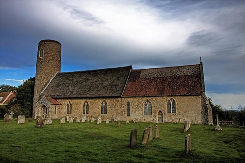
Image by Brokentaco
HDR. AEB +/-3 total of 7 exposures processed with Photomatix.
There was a church in Barsham, at the time of the Domesday Survey, to which belonged twenty acres of glebe, valued at 3s. The patronage was appended to the manor at the above period, and has never been disunited.
The church is dedicated to the Holy Trinity, and comprises a nave and chancel of the same width: the latter is covered with red tiles, but the former, which is somewhat loftier than the chancel, is thatched with reeds, and there is a south por
(Posted from www.automoldchina.com)
A few nice auto mold manufacturers images I found:
Holy Trinity church Barsham Suffolk
Image by Brokentaco
HDR. AEB +/-3 total of 7 exposures processed with Photomatix.
There was a church in Barsham, at the time of the Domesday Survey, to which belonged twenty acres of glebe, valued at 3s. The patronage was appended to the manor at the above period, and has never been disunited.
The church is dedicated to the Holy Trinity, and comprises a nave and chancel of the same width: the latter is covered with red tiles, but the former, which is somewhat loftier than the chancel, is thatched with reeds, and there is a south porch covered with lead. A small north aisle or chapel was taken down about sixty years since, the removal of which has materially injured the stability of the fabric. At the west end of the nave stands a round tower, in which hangs a small solitary bell, though there were three at no very distant period.
The edifice is probably raised upon the site of that mentioned in the Domesday Book, but has no claims to Norman antiquity. The oldest feature discernible in it is a lancet window in the south wall of the chancel, near its junction with the nave, at the lower part of which is a lychnoscope, now plastered over, though the original and massive hinges are visible. The other windows, except that at the east end, are in the style which marks the reign of Edward II., and contain each a single shaft, with here and there a fragment of ancient painted glass. A screen of oak divides the body of the church from the chancel, which must have been erected about the time of James I., if we may judge of its age by the fashion of its design—a bold step at a period so shortly subsequent to the Reformation, and one which must have subjected the Rector to the charge of abetting popery. This incumbent was Joseph Fleming, who held the rectory from 1617 to 1636, and who, as appears by his arms, carved on a corbel, raised the present substantial but inelegant roof of the chancel in 1633. To him, also, I attribute the construction of the eastern window—the most remarkable feature in the edifice. This is formed by stone ribs or mullions, which cross each other diagonally; producing a series of lozenge-shaped lights. On the exterior face of the wall, the diagonal ribs are extended throughout; the interstices, beyond the limits of the glass, being filled with squared flints. The effect is very singular, and in design has, most probably, no parallel. The font, which is coeval with the church, stands in an open space at the west end of the nave.
The Font at Barsham Church.
On the floor of the chancel lies the brass effigy of a warrior, in the military costume of the latter part of the fourteenth century. There are no armorial bearings attached to this monument, and the circumscription is lost, but it must, without doubt, have been placed to the memory of Sir Robert Atte Tye, who was buried here, soon after the year 1380; and whose widow, by will, proved in 1385, desires to be buried in Barsham church, by the side of her late husband. The costume strictly agrees with this appropriation. The present parish clerk, a very aged man, relates a tradition connected with this monument. He says, when this warrior died, four dozens of wine were drank, according to his last directions, over his grave, before the coffin was covered with earth. Strange as such a relation may sound to our ears, it is, in all probability, true. For in the will of James Cooke, of Sporle, in Norfolk, made in 1506, it is ordered, "I will that myn executors, as sone as it may come to ther knouleg that I am dede, that they make a drynkyng for my soul to the value of vis, viiid, in the church of Sporle." The drynkyng was accordingly held in the middle aisle.
An altar-tomb of richly moulded brick stands against the north wall of the chancel. It bears no inscription, but most likely covers the remains of Thomas Blennerhasset, Esq., who was buried in May, 1599.
There are likewise several floor-stones commemorative of former Rectors, and one which especially attracts attention by the variously coloured marbles of which it is composed. It is placed to the memory of the Rev. Thomas Missenden, who died in 1774, after an incumbency of thirty years.
Dr. Maurice Suckling, Prebendary of Westminster Abbey, and Rector of Barsham, was buried here in 1730.
Benjamin Solley, Rector, died Dec. 6, 1714.
Horace Suckling, Clerk, Rector, died April 12, 1828, æt. 57.
There are also monuments to the following persons:
Horace Suckling, youngest son of Robert Suckling, of Woodton, Esq., died August 15, 1751.
William Suckling, Esq., died Dec. 15, 1798, aged 68.
Elizabeth Flavell, eldest daughter of the Rev. Horace Suckling, died July 30, 1833.
Samuel Lillistone, Esq., of Beccles, died June 26, 1829, aged 72.
Eliza Lane, died June 10, 1831.
John Eachard, three times Bailiff of Great Yarmouth, died June 24, 1657. His wife died in the same year.
The Lady Dionesia Atte Tye was buried in the church porch, according to the directions given in her will, in 1375, where a very ancient gravestone, robbed of its brass effigy and armorial bearings, covers her remains.
The register books of Barsham commence in 1558, and down to 1615 were kept in English, and are badly written. After this period another hand occurs, by which the entries are very neatly made, and in Latin. There are a few breaks in the succeeding books, which seem to have been much neglected. In "1559, Thomas, son of Edwarde Tye, was baptized, on the 22nd of Marche." In all probability this was a descendant of the ancient race, formerly Lords of Barsham.
"Anno D’ni 1584. The olde ladie Itchingham was buried the 30th of Julie." The age of this lady is not recorded, but it must have been very advanced, as her youngest daughter, Mary, married John Blennerhasset, Esq., in 1523; and supposing her to have been only forty years old when her youngest daughter was married, she must even so have reached her hundred and first year: but the probability is she was ten or fifteen years older. She was, therefore, with justice called the "olde ladie" Echingham. A good proof this of the salubrity of Barsham Hall, notwithstanding the lowness of its site.
The tithes of the parish have been commuted for £463, and the glebes set at the same time at £160 per annum. These amount to rather more than eighty acres, the land tax on which is redeemed. The churchwarden holds a piece of land producing about 30s. per annum, given for the benefit of the poor, by a benefactor whose name is not recorded.
www.british-history.ac.uk/no-series/suffolk-history-antiq…
High-dynamic-range imaging (HDRI) is a high dynamic range (HDR) technique used in imaging and photography to reproduce a greater dynamic range of luminosity than is possible with standard digital imaging or photographic techniques. The aim is to present a similar range of luminance to that experienced through the human visual system. The human eye, through adaptation of the iris and other methods, adjusts constantly to adapt to a broad range of luminance present in the environment. The brain continuously interprets this information so that a viewer can see in a wide range of light conditions.
HDR images can represent a greater range of luminance levels than can be achieved using more ‘traditional’ methods, such as many real-world scenes containing very bright, direct sunlight to extreme shade, or very faint nebulae. This is often achieved by capturing and then combining several different, narrower range, exposures of the same subject matter. Non-HDR cameras take photographs with a limited exposure range, referred to as LDR, resulting in the loss of detail in highlights or shadows.
The two primary types of HDR images are computer renderings and images resulting from merging multiple low-dynamic-range (LDR) or standard-dynamic-range (SDR) photographs. HDR images can also be acquired using special image sensors, such as an oversampled binary image sensor.
Due to the limitations of printing and display contrast, the extended luminosity range of an HDR image has to be compressed to be made visible. The method of rendering an HDR image to a standard monitor or printing device is called tone mapping. This method reduces the overall contrast of an HDR image to facilitate display on devices or printouts with lower dynamic range, and can be applied to produce images with preserved local contrast (or exaggerated for artistic effect).
In photography, dynamic range is measured in exposure value (EV) differences (known as stops). An increase of one EV, or ‘one stop’, represents a doubling of the amount of light. Conversely, a decrease of one EV represents a halving of the amount of light. Therefore, revealing detail in the darkest of shadows requires high exposures, while preserving detail in very bright situations requires very low exposures. Most cameras cannot provide this range of exposure values within a single exposure, due to their low dynamic range. High-dynamic-range photographs are generally achieved by capturing multiple standard-exposure images, often using exposure bracketing, and then later merging them into a single HDR image, usually within a photo manipulation program). Digital images are often encoded in a camera’s raw image format, because 8-bit JPEG encoding does not offer a wide enough range of values to allow fine transitions (and regarding HDR, later introduces undesirable effects due to lossy compression).
Any camera that allows manual exposure control can make images for HDR work, although one equipped with auto exposure bracketing (AEB) is far better suited. Images from film cameras are less suitable as they often must first be digitized, so that they can later be processed using software HDR methods.
In most imaging devices, the degree of exposure to light applied to the active element (be it film or CCD) can be altered in one of two ways: by either increasing/decreasing the size of the aperture or by increasing/decreasing the time of each exposure. Exposure variation in an HDR set is only done by altering the exposure time and not the aperture size; this is because altering the aperture size also affects the depth of field and so the resultant multiple images would be quite different, preventing their final combination into a single HDR image.
An important limitation for HDR photography is that any movement between successive images will impede or prevent success in combining them afterwards. Also, as one must create several images (often three or five and sometimes more) to obtain the desired luminance range, such a full ‘set’ of images takes extra time. HDR photographers have developed calculation methods and techniques to partially overcome these problems, but the use of a sturdy tripod is, at least, advised.
Some cameras have an auto exposure bracketing (AEB) feature with a far greater dynamic range than others, from the 3 EV of the Canon EOS 40D, to the 18 EV of the Canon EOS-1D Mark II. As the popularity of this imaging method grows, several camera manufactures are now offering built-in HDR features. For example, the Pentax K-7 DSLR has an HDR mode that captures an HDR image and outputs (only) a tone mapped JPEG file. The Canon PowerShot G12, Canon PowerShot S95 and Canon PowerShot S100 offer similar features in a smaller format.. Nikon’s approach is called ‘Active D-Lighting’ which applies exposure compensation and tone mapping to the image as it comes from the sensor, with the accent being on retaing a realistic effect . Some smartphones provide HDR modes, and most mobile platforms have apps that provide HDR picture taking.
Camera characteristics such as gamma curves, sensor resolution, noise, photometric calibration and color calibration affect resulting high-dynamic-range images.
Color film negatives and slides consist of multiple film layers that respond to light differently. As a consequence, transparent originals (especially positive slides) feature a very high dynamic range
Tone mapping
Tone mapping reduces the dynamic range, or contrast ratio, of an entire image while retaining localized contrast. Although it is a distinct operation, tone mapping is often applied to HDRI files by the same software package.
Several software applications are available on the PC, Mac and Linux platforms for producing HDR files and tone mapped images. Notable titles include
Adobe Photoshop
Aurora HDR
Dynamic Photo HDR
HDR Efex Pro
HDR PhotoStudio
Luminance HDR
MagicRaw
Oloneo PhotoEngine
Photomatix Pro
PTGui
Information stored in high-dynamic-range images typically corresponds to the physical values of luminance or radiance that can be observed in the real world. This is different from traditional digital images, which represent colors as they should appear on a monitor or a paper print. Therefore, HDR image formats are often called scene-referred, in contrast to traditional digital images, which are device-referred or output-referred. Furthermore, traditional images are usually encoded for the human visual system (maximizing the visual information stored in the fixed number of bits), which is usually called gamma encoding or gamma correction. The values stored for HDR images are often gamma compressed (power law) or logarithmically encoded, or floating-point linear values, since fixed-point linear encodings are increasingly inefficient over higher dynamic ranges.
HDR images often don’t use fixed ranges per color channel—other than traditional images—to represent many more colors over a much wider dynamic range. For that purpose, they don’t use integer values to represent the single color channels (e.g., 0-255 in an 8 bit per pixel interval for red, green and blue) but instead use a floating point representation. Common are 16-bit (half precision) or 32-bit floating point numbers to represent HDR pixels. However, when the appropriate transfer function is used, HDR pixels for some applications can be represented with a color depth that has as few as 10–12 bits for luminance and 8 bits for chrominance without introducing any visible quantization artifacts.
History of HDR photography
The idea of using several exposures to adequately reproduce a too-extreme range of luminance was pioneered as early as the 1850s by Gustave Le Gray to render seascapes showing both the sky and the sea. Such rendering was impossible at the time using standard methods, as the luminosity range was too extreme. Le Gray used one negative for the sky, and another one with a longer exposure for the sea, and combined the two into one picture in positive.
Mid 20th century
Manual tone mapping was accomplished by dodging and burning – selectively increasing or decreasing the exposure of regions of the photograph to yield better tonality reproduction. This was effective because the dynamic range of the negative is significantly higher than would be available on the finished positive paper print when that is exposed via the negative in a uniform manner. An excellent example is the photograph Schweitzer at the Lamp by W. Eugene Smith, from his 1954 photo essay A Man of Mercy on Dr. Albert Schweitzer and his humanitarian work in French Equatorial Africa. The image took 5 days to reproduce the tonal range of the scene, which ranges from a bright lamp (relative to the scene) to a dark shadow.
Ansel Adams elevated dodging and burning to an art form. Many of his famous prints were manipulated in the darkroom with these two methods. Adams wrote a comprehensive book on producing prints called The Print, which prominently features dodging and burning, in the context of his Zone System.
With the advent of color photography, tone mapping in the darkroom was no longer possible due to the specific timing needed during the developing process of color film. Photographers looked to film manufacturers to design new film stocks with improved response, or continued to shoot in black and white to use tone mapping methods.
Color film capable of directly recording high-dynamic-range images was developed by Charles Wyckoff and EG&G "in the course of a contract with the Department of the Air Force". This XR film had three emulsion layers, an upper layer having an ASA speed rating of 400, a middle layer with an intermediate rating, and a lower layer with an ASA rating of 0.004. The film was processed in a manner similar to color films, and each layer produced a different color. The dynamic range of this extended range film has been estimated as 1:108. It has been used to photograph nuclear explosions, for astronomical photography, for spectrographic research, and for medical imaging. Wyckoff’s detailed pictures of nuclear explosions appeared on the cover of Life magazine in the mid-1950s.
Late 20th century
Georges Cornuéjols and licensees of his patents (Brdi, Hymatom) introduced the principle of HDR video image, in 1986, by interposing a matricial LCD screen in front of the camera’s image sensor, increasing the sensors dynamic by five stops. The concept of neighborhood tone mapping was applied to video cameras by a group from the Technion in Israel led by Dr. Oliver Hilsenrath and Prof. Y.Y.Zeevi who filed for a patent on this concept in 1988.
In February and April 1990, Georges Cornuéjols introduced the first real-time HDR camera that combined two images captured by a sensor3435 or simultaneously3637 by two sensors of the camera. This process is known as bracketing used for a video stream.
In 1991, the first commercial video camera was introduced that performed real-time capturing of multiple images with different exposures, and producing an HDR video image, by Hymatom, licensee of Georges Cornuéjols.
Also in 1991, Georges Cornuéjols introduced the HDR+ image principle by non-linear accumulation of images to increase the sensitivity of the camera: for low-light environments, several successive images are accumulated, thus increasing the signal to noise ratio.
In 1993, another commercial medical camera producing an HDR video image, by the Technion.
Modern HDR imaging uses a completely different approach, based on making a high-dynamic-range luminance or light map using only global image operations (across the entire image), and then tone mapping the result. Global HDR was first introduced in 19931 resulting in a mathematical theory of differently exposed pictures of the same subject matter that was published in 1995 by Steve Mann and Rosalind Picard.
On October 28, 1998, Ben Sarao created one of the first nighttime HDR+G (High Dynamic Range + Graphic image)of STS-95 on the launch pad at NASA’s Kennedy Space Center. It consisted of four film images of the shuttle at night that were digitally composited with additional digital graphic elements. The image was first exhibited at NASA Headquarters Great Hall, Washington DC in 1999 and then published in Hasselblad Forum, Issue 3 1993, Volume 35 ISSN 0282-5449.
The advent of consumer digital cameras produced a new demand for HDR imaging to improve the light response of digital camera sensors, which had a much smaller dynamic range than film. Steve Mann developed and patented the global-HDR method for producing digital images having extended dynamic range at the MIT Media Laboratory. Mann’s method involved a two-step procedure: (1) generate one floating point image array by global-only image operations (operations that affect all pixels identically, without regard to their local neighborhoods); and then (2) convert this image array, using local neighborhood processing (tone-remapping, etc.), into an HDR image. The image array generated by the first step of Mann’s process is called a lightspace image, lightspace picture, or radiance map. Another benefit of global-HDR imaging is that it provides access to the intermediate light or radiance map, which has been used for computer vision, and other image processing operations.
21st century
In 2005, Adobe Systems introduced several new features in Photoshop CS2 including Merge to HDR, 32 bit floating point image support, and HDR tone mapping.
On June 30, 2016, Microsoft added support for the digital compositing of HDR images to Windows 10 using the Universal Windows Platform.
HDR sensors
Modern CMOS image sensors can often capture a high dynamic range from a single exposure. The wide dynamic range of the captured image is non-linearly compressed into a smaller dynamic range electronic representation. However, with proper processing, the information from a single exposure can be used to create an HDR image.
Such HDR imaging is used in extreme dynamic range applications like welding or automotive work. Some other cameras designed for use in security applications can automatically provide two or more images for each frame, with changing exposure. For example, a sensor for 30fps video will give out 60fps with the odd frames at a short exposure time and the even frames at a longer exposure time. Some of the sensor may even combine the two images on-chip so that a wider dynamic range without in-pixel compression is directly available to the user for display or processing.
en.wikipedia.org/wiki/High-dynamic-range_imaging
Read more about Nice Auto Mold Manufacturers photos
(Posted from www.automoldchina.com)
Some cool auto moulds manufacturers china images:
Read more about Nice Auto Moulds Manufacturers China photos
(Posted from www.automoldchina.com)
Some cool auto moulds manufacturers china images:
Read more about Nice Auto Moulds Manufacturers China photos
(Posted from www.automoldchina.com)
A few nice automotive interior mold suppliers images I found:
Read more about Nice Automotive Interior Mold Suppliers photos
(Posted from www.automoldchina.com)
A few nice automotive interior mold suppliers images I found:
Read more about Nice Automotive Interior Mold Suppliers photos
(Posted from www.automoldchina.com)
Check out these china auto moulds manufacturers images:
Read more about Nice China Auto Moulds Manufacturers photos
(Posted from www.automoldchina.com)
Check out these china auto moulds manufacturers images:
Read more about Nice China Auto Moulds Manufacturers photos
(Posted from www.automoldchina.com)
Some cool automotive parts mold images:
Kevlar fibre composite shear surface
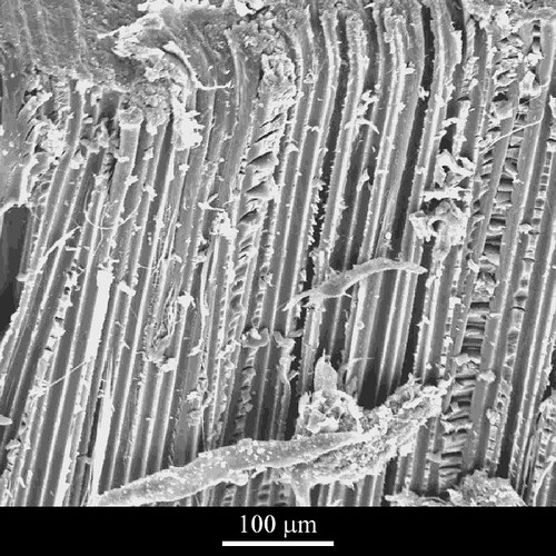
Image by CORE-Materials
DoITPoMS, University of Cambridge
This is an image of the shear surface in a failed composite beam. ‘Hackles’ of matrix are clearly visible where shear has occurred within the matrix and it is also clear that shear has occurred across the fibre/matrix interface. The fibres are for the most part totally unscathed, though some mis-aligned fibres have become caught between the shear surfaces and ‘fibrillated’ by rolling and bending act
(Posted from www.automoldchina.com)
Some cool automotive parts mold images:
Kevlar fibre composite shear surface
Image by CORE-Materials
DoITPoMS, University of Cambridge
This is an image of the shear surface in a failed composite beam. ‘Hackles’ of matrix are clearly visible where shear has occurred within the matrix and it is also clear that shear has occurred across the fibre/matrix interface. The fibres are for the most part totally unscathed, though some mis-aligned fibres have become caught between the shear surfaces and ‘fibrillated’ by rolling and bending actions. It may be that this failure mechanism has been partly inhibited by poor fibre alignment since some off-axis fibres will reinforce the matrix in shear. It will have been promoted, however, by the extensive longitudinal voids.
System
Kevlar composite
Composition
Kevlar fibre, epoxy resin matrix
Reaction
Kevlar is a lyotropic liquid crystal polymer. This means that it can be readily processed in solution (in this case, sulphuric acid). It is annealed under tension to increase its elastic modulus
Processing
A crude Kevlar composite was made by laying out 40 tows of fibre, painting them with epoxy resin, compressing them in a mould, and curing them for five hours at 100-190 degrees C
Applications
Kevlar composites are used as a structural material in the aerospace and automotive industries, as well as in certain high-performance sporting equipment. They present exceptional stiffness and can be structurally optimised for particular load-bearing applications.
Sample preparation
The bar has been bent to failure in a three-point bending rig.
Technique
Scanning electron microscopy (SEM)
Contributor
J A Curran
Organisation
Department of Materials Science and Metallurgy, University of Cambridge
View micrograph in DoITPoMS website
Image from page 935 of “Automotive industries” (1899)
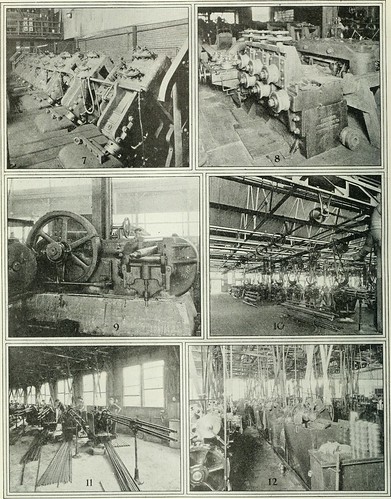
Image by Internet Archive Book Images
Identifier: automotiveindust44phil
Title: Automotive industries
Year: 1899 (1890s)
Authors:
Subjects: Automobiles Aeronautics
Publisher: Philadelphia [etc.] Chilton [etc.]
Contributing Library: Engineering – University of Toronto
Digitizing Sponsor: University of Toronto
View Book Page: Book Viewer
About This Book: Catalog Entry
View All Images: All Images From Book
Click here to view book online to see this illustration in context in a browseable online version of this book.
Text Appearing Before Image:
(1) One of a battery of four modern electric furnaces with a daily capacity of slif/htly more than 150 tons. (2) Pouring■ ■■:,■■■■ •■/ into ,„,,,,/ moulds ,„ the Timhen steel will. ( ?,, 11 ,,,1 ran I ir press ami electric manipulator where inuots arepressed into blooms. (4) Twenty-two inch, three stand rolling mill and tilting tables where blooms are converted intorounds and squares with a size range of from 2 in. to 6% in. (5) Twelve inch, three-stand rolling mill where bars for rollsare converted into coils and small rods. (6) Piercing mill where bars are converted into seamless tubes. 914 AUTOMOTIVE INDUSTRIESTHE AUTOMOBILE April 28, 1921
Text Appearing After Image:
there pierced seamless tubes are automatically finished. (8) Straightening machine where finished traii/lttened. (9) Bulldozer for fabrication of formed seamless tubes. (10) Part of the screw machine nibesare fabricated on automatic screw machines into green cups and cones. (11) Four spindle roller fuhrictihit,/ much nies where rods tire fabricated al high speed into <• rarictij a) si cs o) rolls held to much tiling tolerances not in excess of .003 of an inch. (12) Another view of the screw machine department where large cups and cones made from forgings are machined on automatic screw machines. (7) Reducing millseamless tubes aredepartment win re tul April 28, 1921 AUTOMOTIVE INDUSTRIES THE AUTOMOBILE 915
Note About Images
Please note that these images are extracted from scanned page images that may have been digitally enhanced for readability – coloration and appearance of these illustrations may not perfectly resemble the original work.
4 remaining days of Major Project
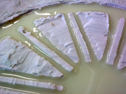
Image by Matty Ring
The whiter coloured material is a mould made of silicon rubber, for the rims on my car. the yellow material is two part plastic.
Read more about Nice Automotive Parts Mold photos
(Posted from www.automoldchina.com)
Check out these automotive parts mold images:
Smart Doll Stand Material
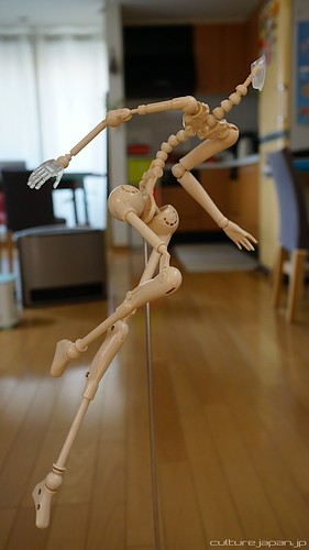
Image by Danny Choo
The fixture in the back is removable but allows a stand to be mounted which allows dynamic poses like this one.
The frame is made from durable Polyoxymethylene – the following blurb about this material copied from WIkipedia.
Typical applications for injection-molded POM include high performance engineering components such as small gear wheels, ball bearings, ski bindings, fasteners, knife handles, lock systems, and model rocket launch buttons. The material is widely used in the automotive and consumer electronics industry.
(Posted from www.automoldchina.com)
Check out these automotive parts mold images:
Smart Doll Stand Material
Image by Danny Choo
The fixture in the back is removable but allows a stand to be mounted which allows dynamic poses like this one.
The frame is made from durable Polyoxymethylene – the following blurb about this material copied from WIkipedia.
Typical applications for injection-molded POM include high performance engineering components such as small gear wheels, ball bearings, ski bindings, fasteners, knife handles, lock systems, and model rocket launch buttons. The material is widely used in the automotive and consumer electronics industry. The M-16 rifle’s stock and other parts are made of it.
View more at www.dannychoo.com/en/post/27135/Smart+Doll+Manual+Version…
Read more about Nice Automotive Parts Mold photos
(Posted from www.automoldchina.com)
A few nice automobile molds manufacturers images I found:
1934 Delage D8SS

Image by glennfrancosimmons_
This car was really hard to get good photos of because Blackhawk’s second-floor gallery is so dark. Eventually, I’ll see if I have better ones than these.
Blackhawk Automotive Museum contains masterpieces as elegant as any that you will find in the finest museums the world over.
If you believe that statement to be filled with a hubris of hyperbole, then you are probably not a classic-car lover and mistake automotive masterpieces as unworthy of being considered art. Yet it is art. I’ve oft
(Posted from www.automoldchina.com)
A few nice automobile molds manufacturers images I found:
1934 Delage D8SS
Image by glennfrancosimmons_
This car was really hard to get good photos of because Blackhawk’s second-floor gallery is so dark. Eventually, I’ll see if I have better ones than these.
Blackhawk Automotive Museum contains masterpieces as elegant as any that you will find in the finest museums the world over.
If you believe that statement to be filled with a hubris of hyperbole, then you are probably not a classic-car lover and mistake automotive masterpieces as unworthy of being considered art. Yet it is art. I’ve often mentioned this when discussing Blackhawk.
Already more than two decades young, Blackhawk has gained an international reputation for its legendary automotive collection.
One of the finest vehicles in its galleries is this 1934 Delage D8SS — the only one of its kind ever made.
And Blackhawk has it, in addition to many other very, very rare vehicles.
Not only were Delage autos among the finest ever made in France, but they were renown the world over for their artistic symmetry.
Of the Delages produced, the finest masterpiece was the D8 with its four-liter straight-eight engine that was introduced at the Paris Salon in October 1929, with production continuing until 1933.
The D8 was an auto of elegance and beauty, as you can see by these photos.
Blackhawk said such attributes inspired "coachbuilders," as auto designers were then called, "to create their most-stylish designs."
The D8 developed into the D8S, a 102-hp engine, only to have a power increase up to 118-hp at 3,800 rpm, according to Blackhawk.
Not content with that, the D8SS had a power increase up to 145 hp at 4,500 rpm. One could call it speedy elegance.
Just imagine taking this beauty on a coastal ride up or down Highway 1.
The beautiful coachwork in this Delage resulted from a partnership with the skillful coachbuilders Fernandez & Darrin that reached its golden age with this special model.
"The coachbuilding firm of Fernandez & Darrin was formed through a partnership between American designer Howard ‘Dutch’ Darrin and Mr. Fernandez, a Parisian banker," Blackhawk notes.
Darrin was a former partner of the Hibbard & Darrin coachbuilding company, which Blackhawk said created "concours-winning body designs for the chassis of Europe’s most-prestigious luxury marques."
The beautifully elegant cabriolet shown in this post "has a removable panel over its front seat and length that is accented with polished aluminum on the hood and belt molding," Blackhawk notes.
"The Lalique crystal radiator mascot, ‘Tete de paon,’ depicts the proud peacock’s head in profile," Blackhawk states.
Engine:
7-cylinder, straight-eight, OHV
3.03" bore, 4.29" stroke
247 cubic inch
145 hp at 4,500 rpm
Body/Coachbuilder
Fernandez & Darrin
Paris, France.
Manufacturer
Automobiles Delage,
Courbevoie, Seine, France
Price when new: ,000 (chassis only in 1934 dollar valuation).
1930 Pierce Arrow Model B Victoria Coupe
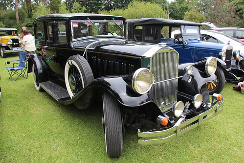
Image by Sicnag
Pierce Arrow Motor Car Company was an American automobile manufacturer based in Buffalo, New York, which was active from 1901 to 1938. Although best known for its expensive luxury cars, Pierce-Arrow also manufactured commercial trucks, fire trucks, camp trailers, motorcycles, and bicycles.
Early cars had the largest automobile engines in the world. In 1914 Pierce-Arrow adopted its most enduring styling hallmark when its headlights were moved from a traditional placement on either side of the radiator into flared housings molded into the front fenders of the car, this hallmark carried through to the last model in 1938.
In 1928 Studebaker took over Pierce Arrow.
For 1930 Pierce introduced the A, B, and C models. The A was the largest and most expensive, while the C was the cheapest of the three. Customers had four wheelbase sizes to select from, including 132, 134, 139 and 144 inches
Model B Engine; 125hp 365 cu in 6 cyl
Read more about Nice Automobile Molds Manufacturers photos
(Posted from www.automoldchina.com)
Some cool auto interior mould manufacturers images:
Read more about Nice Auto Interior Mould Manufacturers photos
(Posted from www.automoldchina.com)
Some cool auto interior mould manufacturers images:
Read more about Nice Auto Interior Mould Manufacturers photos


